7. Use the magnifier to measure the width (W) of ten grooves whose edges have been marked by the tool. This may be done by lining up the long vertical zero line on the magnifier scale along the left edge of each groove (i.e. along the middle of the bright line scratched by the tool) and reading off the position of the other edge on the portion of the magnifier scale which reads to 0.005 inches or 0.1 mm. For best results the scratched line should be about 0.005 inches or 0.1 mm wide, in which case each measurement can be made to the nearest 0.002 inches or 0.05 mm (e.g. 0.65 mm, 0.80 mm). If it is appreciably wider than 0.005 inches or 0.1 mm, then too much pressure has been applied in using the marking tool. In that case abandon that particular part of the groove and do a repeat “ink and scratch” a little to one side.
Record all ten groove widths. Often they will be the same, or differ by only 0.002 inches or 0.05 mm.
Calculate and record the average width, Wav; note the largest measured width, Wmax.
Note the second largest width, and the second smallest. Calculate the difference between them, and record it as Wvar (“Width variation”).
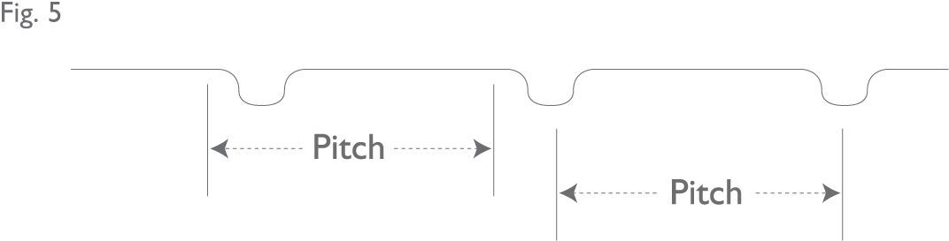
8. Determine the pitch of the grooves – the distance from a specific point on a groove to the same on the next groove, for example centre to centre, or left edge to left edge (See Figure 5).
This measurement can be made either with the steel ruler or with the magnifier; but, in most cases, the steel ruler is the more convenient. Measure the left edge to left edge distance from groove 1 to groove 11 (or 2 to 12 etc), and divide this distance by 10 to arrive at the pitch, P. If a ten groove span is not available, then nine or eight will be satisfactory (but remember to divide by the appropriate number to find P).
Alternatively, and this is the only option if a span of fewer than eight grooves is available, you can use the magnifier. Measure the distance from one edge of groove 1 to the corresponding edge of groove 5. The best way to do this is to position the long zero line of the magnifier scale on the left edge of groove 3 then read off the distances on either side of it to grooves 1 and 5 and add them together. You can, of course, use any two grooves spaced four apart (e.g. 3 and 7, or 6 and 10); indeed, it may be as well to check your first measurement by repeating the procedure with another such pair of grooves.
It is good enough to make this measurement to the nearest 0.005 inches or 0.1 mm. Then divide the measured span of four grooves by 4 to give the pitch, P.
Whichever method is used, the object is to get the best possible measure of the average groove pitch (P).
At this stage it may be worth checking your average by measuring the pitch from one groove to the next one, e.g. grooves 1 to 2, or 5 to 6. If these measurements differ from the average by more than 0.005 or 0.1 mm, then either you calculated the average incorrectly (check it), or the grooves are unevenly spaced. In the latter event you must measure the grooves differently (see Section 14).