Interpretation of Rule 2.a
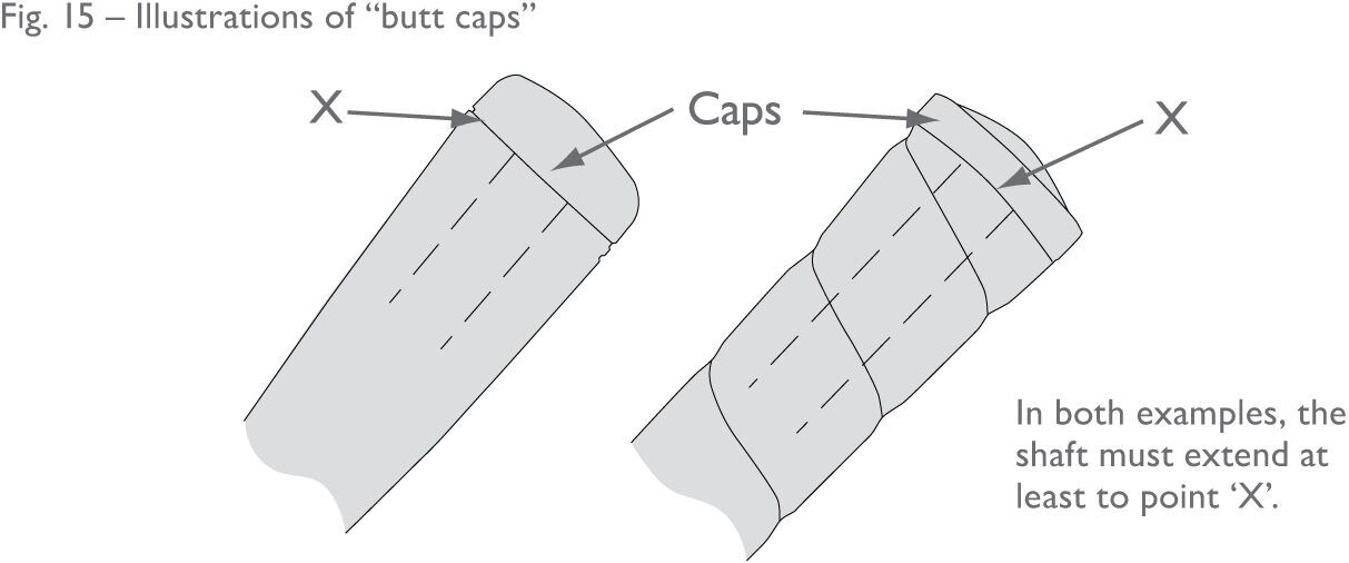
This provision is interpreted to mean that the shaft must extend to the end of the
grip, or at least that the grip should not extend beyond the top end of the shaft
more than is necessary to accommodate the butt cap (see Figure 15).

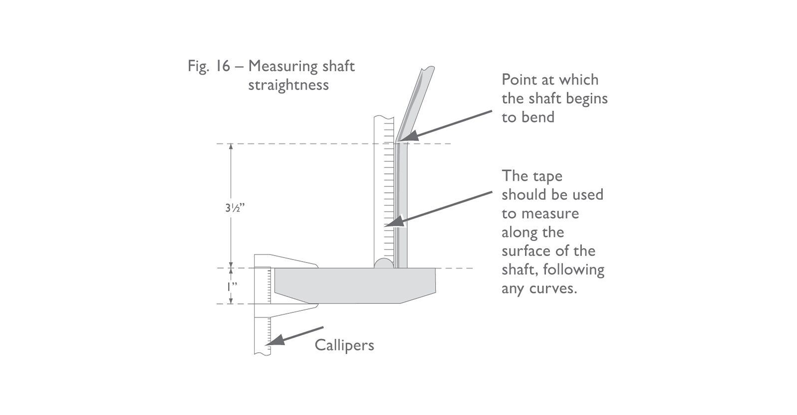
The “5-inch” measurement should be made using a pair of callipers (to measure the
depth of the head at the point where the shaft is attached) and a flexible measuring
tape, or a piece of string (to measure the length of any bend or bends in the shaft
from the point where the shaft ceases to be straight) (see Figure 16).

The point where the shaft ceases to be straight can be determined by placing a rigid
steel ruler along the straight part of the shaft and marking the point where the shaft
and the ruler are no longer in contact. This provision is particularly relevant to
putters where the shaft is inserted directly into the head. (For putter heads that
have a “neck” – see Section 2c).
Interpretation of Rule 2.b
This provision effectively restricts shafts from being designed to have asymmetric
properties, so that irrespective of how the club is assembled, or whichever way the
shaft is orientated, it will make no difference to the performance of the club. Clause
(i) is interpreted to mean that the way in which the shaft deflects must be the same
regardless of its orientation. It is not simply a measure of the magnitude of deflection.
It is challenging to assess the conformance of a shaft in the field. However, a standard
shaft with a circular cross-section would most likely conform unless there is specific
evidence to the contrary (e.g. claims by the manufacturer which indicate non-conformance,
including advertising claims). A shaft which is not symmetrical in all axes (e.g.
a shaft with an oval or rectangular cross-section) would not normally be expected
to conform to the Equipment Rules. Manufacturers of shafts with unusual cross-sections
or other unique features should submit them to The R&A or USGA for a ruling prior
to marketing and/or manufacturing. Whether such a ruling exists can be confirmed by
contacting The R&A or USGA.
Many graphite shafts have a small “spine” or “spines” running along the length of
the shaft which may make them bend a little differently depending on how they are
oriented during installation. The existence of a small spine is generally regarded
as being the result of normal manufacturing processes and therefore not a breach of
Section 2b. As previously noted, The R&A and USGA recognizes that it is difficult
to produce a perfectly symmetrical shaft. Therefore, provided that the shaft is manufactured
with the intention of meeting the above requirement, a reasonable tolerance is applied
when evaluating shafts for conformance.
Manufacturers of clubs may orientate or align shafts which have spines for uniformity
in assembling sets or in an effort to make the shafts perform as if they were perfectly
symmetrical. However, a shaft which has been orientated for the purpose of influencing
the performance of a club, e.g. to correct wayward shots, would be contrary to the
intent of this provision.
Interpretation of Rule 2.c
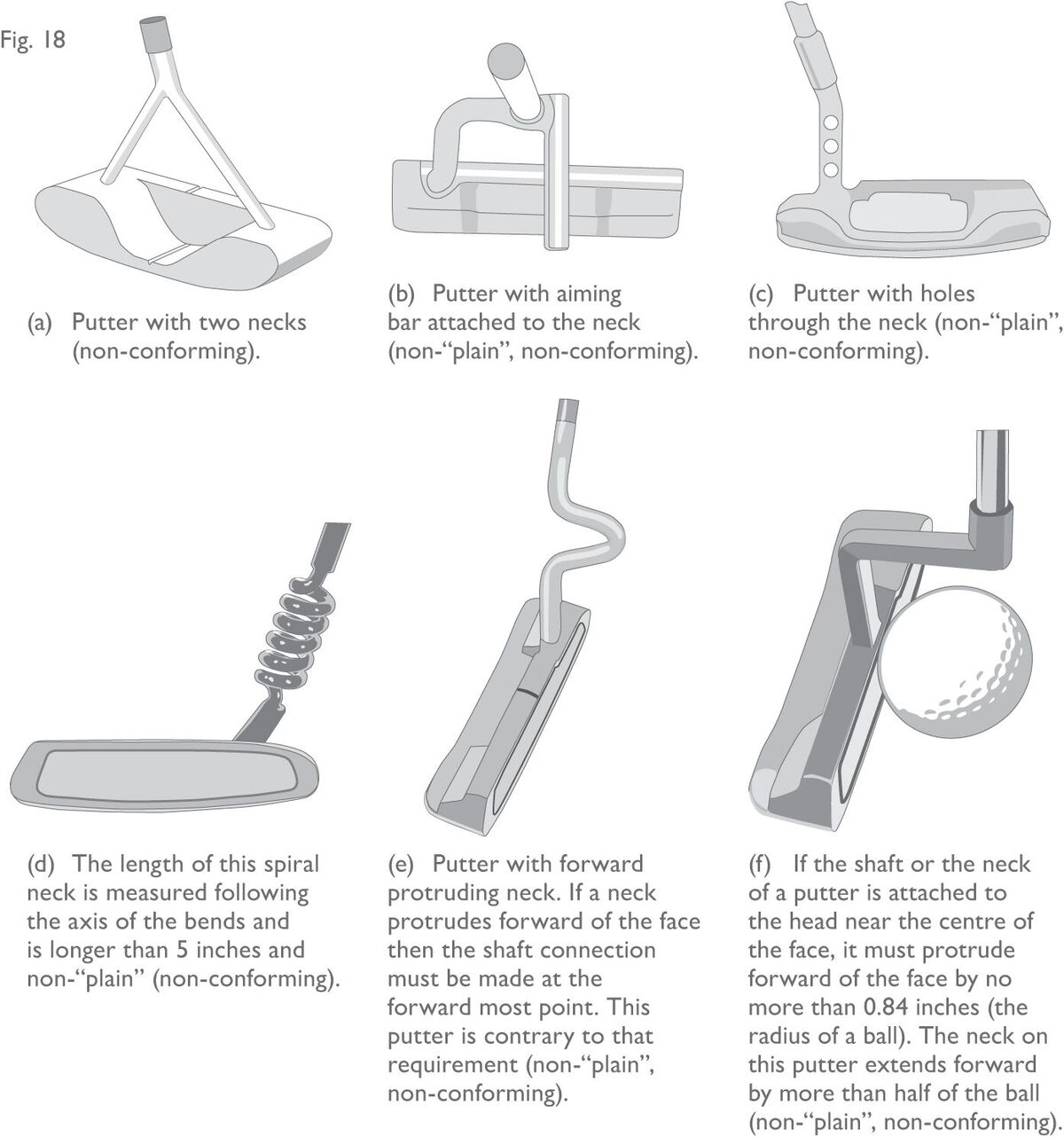
The most important points to remember here are that a club must only have one neck,
that it must be “plain” and, in order to restrict elaborate shapes and curves, the
length of the neck is limited to 5 inches (127 mm).
The interpretation of a “plain” neck is clarified as follows:
2.c(1) - All clubs
The neck must not be shaped for any purpose, other than connecting the shaft to the
head in a traditional manner. While a neck may contain features such as an adjustability
mechanism, a method for damping vibration or an alignment line, it must not be unusually
shaped in order to house or accommodate such a feature. For example, in most cases,
lines which have been painted or lightly engraved onto an otherwise plain neck are
permitted. However, a neck designed specifically to accommodate such lines or marks
would be considered non-conforming. Small scale features, on an otherwise plain neck,
which are purely for decorative purposes, and could not effectively perform, or be
used for, another purpose, may also be permitted.
2.c(2) - Woods
The above requirements also apply to woods, however there is some accommodation for
the transition area between the head of a wood and its neck. This transition area
must fit within a cylinder of a diameter and height of 1 inch (25.4 mm) measured from
the base of the transition and parallel to the axis of the shaft. Any transition which
satisfies this restriction should be permitted provided it does not contain any other
non-plain feature (for example, holes or alignment bars).
NOTE: Some exceptions may be made for clubheads made of wood. Ferrules shaped to circumvent
this interpretation are not permitted.
2.c(3) - Neck Length Measurement
The measurement of the length of a neck should be made in the same way as a bend in
the bottom of a shaft (see Section 2a and Figure 16).
The majority of necks are designed to have the shaft inserted into them, and this
normally avoids any confusion as to where the neck begins. However, if the neck is
inserted into the shaft, the measurement should be taken from the end of the shaft.
Figure 18 contains diagrams of various neck features which would not be permitted.


